ブックタイトルPIPE HANGERS & SUPPORTS
- ページ
- 9/92
このページは PIPE HANGERS & SUPPORTS の電子ブックに掲載されている9ページの概要です。
秒後に電子ブックの対象ページへ移動します。
「ブックを開く」ボタンをクリックすると今すぐブックを開きます。
このページは PIPE HANGERS & SUPPORTS の電子ブックに掲載されている9ページの概要です。
秒後に電子ブックの対象ページへ移動します。
「ブックを開く」ボタンをクリックすると今すぐブックを開きます。
PIPE HANGERS & SUPPORTS
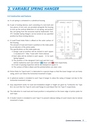
2.4 Construction and Features(a) A coil spring is contained in a cylindrical housing.(b) A pair of locking devices, each consisting of a lock bolt andfour pieces of lock nuts, are provided alongside the housingto lock up the vertical deflection of coil spring, and protectthe coil spring from the excessive load by Hydrostatic Test.STC Variable Spring Hangers can be locked at any specifiedposition by these locking devices.(c) A Load/Travel Index Plate is affixed on the outer surface ofthe housing.The amount of load and travel is pointed on the index plateby an indicator of the piston plate.The specifications on this index plate are;1) Design Load at position will be etched in each square① located at 0 ~ Max. Travel with 15mm interval.2) Each data will be etched in each square ② for eachSpring Support.3) The position of the designed Cold Load and Hot Loadwill be marked by each seal (sticker) C (blue) and H (red) respectively.4) A mark of passing inspection will be die-stamped at square ④ .5) The surface of Plate is Black and the printed letters are silver color.(d) Piston Plate for Type B and C is fabricated in a special shape so that the lower hanger rod can freelyswing, and it can follow the horizontal movement of pipe.(e) A spherical washer is installed to each Type D hanger to allow the swing of hanger rod due to thehorizontal movement of pipe.(f) Easy adjustment works for load and installation length or height are given by Turnbuckle (for TypeB,C), by Lock Nut (for Type D) and Load Flange & Load Adjust Nut (for Type F) respectively.(g) The indication to read load and travel position is red-painted on the lower edge of piston plate foreach type.(h) A Guide Column is installed to each Type F to prevent sideway falling of Load Column due to lateralmovement of pipe.2. VARIABLE SPRING HANGER8