ブックタイトルHYDRAULIC SNUBBERS
- ページ
- 13/48
このページは HYDRAULIC SNUBBERS の電子ブックに掲載されている13ページの概要です。
秒後に電子ブックの対象ページへ移動します。
「ブックを開く」ボタンをクリックすると今すぐブックを開きます。
このページは HYDRAULIC SNUBBERS の電子ブックに掲載されている13ページの概要です。
秒後に電子ブックの対象ページへ移動します。
「ブックを開く」ボタンをクリックすると今すぐブックを開きます。
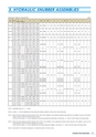
HYDRAULIC SNUBBERS
Dimension Table for Type EA/FA (mm)Size Stroke L1(Min.)L1(Max.) L2 A1 A2 K OA M OD E E1 F1 G OH R1 R2 U1 U2 B T aSN-03100 642 1,340 563 500 501 255160 732 1,340 653 590 591 315 76.3 M16 12 49 28 50 55.5 27.2 18.0 19.0 62 44 47 22 4250 867 1,340 788 725 726 405SN-06100 659 1,567 573 517 511 255160 749 1,567 663 607 601 315 89.1 M20 12 56 35 50 61.5 34.0 20.0 19.0 62 48 47 22 4250 884 1,567 798 742 736 405SN - 1100 683 1,718 580 524 511 250160 773 1,718 670 614 601 310 101.6 M20 15 68 44 55 68.5 42.7 24.0 25.0 69 48 52 26 4250 908 1,718 805 749 736 400SN - 3100 811 1,917 671 611 591 293139.8 M3017 94 6274 87.560.5 31.5 32.580 5873.5 31.5 4160 901 1,917 761 701 681 353250 1,036 1,917 896 836 816 443310 1,126 - 986 926 906 503400 1,321 ー1,199 1,121 1,114 638460 1,411 ー 1,289 1,211 1,204 698 165.2 M36 87 100.5 85 64550 1,546 ー1,424 1,346 1,339 788SN - 6100 906 2,152 749 691 664 338165.2 M3625 114 7887 100.576.3 41.5 37.585 6480 34 6160 996 2,152 839 781 754 398250 1,131 2,152 974 916 889 488310 1,221 ー1,064 1,006 979 548400 1,356 ー1,199 1,141 1,114 638460 1,446 ー1,289 1,231 1,204 698550 1,628 ー1,492 1,400 1,394 810 190.7 M42 108 113.5 98 70SN-10100 1,002 2,405 817 744 719 360190.7 M4230 133 91108 113.589.1 54.0 50.098 7097 38 8160 1,092 2,405 907 834 809 420250 1,227 2,405 1,042 969 944 510310 1,317 ー1,132 1,059 1,034 570400 1,452 ー1,267 1,194 1,169 660460 1,608 ー1,445 1,331 1,328 753 216.3 M48 130 126.5 117 76550 1,799 ー1,666 1,506 1,533 868 267.4 M56 160 152.5 133 84SN-16100 1,130 3,024 905 823 788 393216.3 M4840 165 116130 126.5114.3 63.0 62.5117 76116 47 10160 1,220 3,024 995 913 878 453250 1,355 3,024 1,130 1,048 1,013 543310 1,445 ー1,220 1,138 1,103 603400 1,636 ー1,441 1,313 1,308 718460 1,726 ー 1,531 1,403 1,398 778 267.4 M56 160 152.5 133 84550 1,861 ー1,666 1,538 1,533 868SN-25100 1,256 3,497 991 893 858 418267.4 M56 50 195 142 160 152.5 139.8 73.0 75.0 133 84 139 68 12160 1,346 3,497 1,081 983 948 478250 1,481 3,497 1,216 1,118 1,083 568310 1,571 ー1,306 1,208 1,173 628400 1,706 ー1,441 1,343 1,308 718NOTE 1. Adjustable range of U2 = +/- 25mmNOTE 2. L1(Min.), L2, A1 and A2 dimensions are those when the indicator position is at the center of the total stroke.NOTE 3. When the piston design movement direction (from Cold to Hot condition) is the extension direction (plus direction), the snubber is pre-set at the strokeposition 25mm from the fully retracted end of stroke.In this case, the L1(Min.), L2, A1 and A2 dimensions are the value obtained by subtracting [ (Total Stroke / 2) - 25mm ] from the values in the above table.NOTE 4. When the piston design movement direction (from Cold to Hot condition) is the compression direction (minus direction), the snubber is pre-set at thestroke position 25mm from the fully extended end of stroke.In this case, the L1(Min.), L2, A1 and A2 dimensions are the value obtained by adding [ (Total Stroke / 2) - 25mm ] from the values in the above table.NOTE 5. Check with STC for the Max. Dimensions of L1 when the stroke is 310 mm or more.3. HYDRAULIC SNUBBER ASSEMBLIES12