ブックタイトルHYDRAULIC SNUBBERS
- ページ
- 15/48
このページは HYDRAULIC SNUBBERS の電子ブックに掲載されている15ページの概要です。
秒後に電子ブックの対象ページへ移動します。
「ブックを開く」ボタンをクリックすると今すぐブックを開きます。
このページは HYDRAULIC SNUBBERS の電子ブックに掲載されている15ページの概要です。
秒後に電子ブックの対象ページへ移動します。
「ブックを開く」ボタンをクリックすると今すぐブックを開きます。
HYDRAULIC SNUBBERS
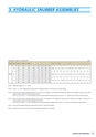
3. HYDRAULIC SNUBBER ASSEMBLIESDimension Table for Type EB/FB (mm)Type Size Stroke L1(Min.) L1(Max.) L2 A1 A2 K F OA M OD E E1 OH R T G U1 U2 aEB,FB40100 1,297 1,920 1,110 1,052 639 385 299160 1,387 2,010 1,260 1,142 729 445 359 238 60 60 241 70 139.8 80 56 150 172 73 16250 1,522 2,145 1,485 1,277 864 535 44960100 1,472 2,020 1,223 1,187 679 415 348160 1,562 2,110 1,373 1,277 769 475 408 280 68 70 312 80 165.2 93 65 170 196 79 20250 1,697 2,245 1,598 1,412 904 565 498100100 1,651 2,155 1,357 1,306 727 445 399160 1,741 2,245 1,507 1,396 817 505 459 326 80 80 348 90 216.3 118 75 195 231 89 25250 1,876 2,380 1,732 1,531 952 595 549NOTE 1. Adjustable range of U2 = +/- 25mmNOTE 2. L1(Min.), L2, A1 and A2 dimensions are those when the indicator position is at the center of the total stroke.NOTE 3. When the piston design movement direction (from Cold to Hot condition) is the extension direction (plus direction), the snubber is pre-set at the strokeposition 25mm from the fully retracted end of stroke.In this case, the L1(Min.), L2, A1 and A2 dimensions are the value obtained by subtracting [(Total Stroke / 2) - 25mm] from the values in the above table.NOTE 4. When the piston design movement direction (from Cold to Hot condition) is the compression direction (minus direction), the snubber is pre-set at thestroke position 25mm from the fully extended end of stroke.In this case, the L1(Min.), L2, A1 and A2 dimensions are the value obtained by adding [(Total Stroke / 2) - 25mm] from the values in the above table.NOTE 5. Collars will be supplied along with Bracket and/or Clamps for type EB/FB Snubbers.NOTE 6. Clamps for size 40, 60, and 100 are specially designed and supplied in each request.14