ブックタイトルHYDRAULIC SNUBBERS
- ページ
- 17/48
このページは HYDRAULIC SNUBBERS の電子ブックに掲載されている17ページの概要です。
秒後に電子ブックの対象ページへ移動します。
「ブックを開く」ボタンをクリックすると今すぐブックを開きます。
このページは HYDRAULIC SNUBBERS の電子ブックに掲載されている17ページの概要です。
秒後に電子ブックの対象ページへ移動します。
「ブックを開く」ボタンをクリックすると今すぐブックを開きます。
HYDRAULIC SNUBBERS
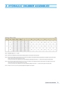
3. HYDRAULIC SNUBBER ASSEMBLIESDimension Table for Type G (mm)Type Size Stroke L(Min.) L(Max.) A2 K OA M OD F OH R T U2G40100 1,095 1,920 800 310160 1,185 2,010 890 370 340 72 60 180 165.2 95 76 100250 1,320 2,145 1,025 46060100 1,180 2,020 870 335160 1,270 2,110 960 395 375 80 70 210 216.3 115 86 110250 1,405 2,245 1,095 485100100 1,300 2,155 970 375160 1,390 2,245 1,060 435 425 90 80 250 267.4 155 96 120250 1,525 2,380 1,195 525NOTE 1. Adjustable range of U2 = +/- 25mmNOTE 2. L(Min.) and A2 dimensions are those when the indicator position is at the center of the total stroke.NOTE 3. When the piston design movement direction (from Cold to Hot condition) is the extension direction (plus direction), the snubber is pre-set at the strokeposition 25mm from the fully retracted end of stroke.In this case, the L(Min.) and A2 dimensions are the value obtained by subtracting [(Total Stroke / 2) - 25mm] from the values in the above table.NOTE 4. When the piston design movement direction (from Cold to Hot condition) is the compression direction (minus direction), the snubber is pre-set at thestroke position 25mm from the fully extended end of stroke.In this case, the L(Min.) and A2 dimensions are the value obtained by adding [(Total Stroke / 2) - 25mm] from the values in the above table.NOTE 5. Clamps for size 40, 60, and 100 are specially designed and supplied in each request.16