ブックタイトルHYDRAULIC SNUBBERS
- ページ
- 9/48
このページは HYDRAULIC SNUBBERS の電子ブックに掲載されている9ページの概要です。
秒後に電子ブックの対象ページへ移動します。
「ブックを開く」ボタンをクリックすると今すぐブックを開きます。
このページは HYDRAULIC SNUBBERS の電子ブックに掲載されている9ページの概要です。
秒後に電子ブックの対象ページへ移動します。
「ブックを開く」ボタンをクリックすると今すぐブックを開きます。
HYDRAULIC SNUBBERS
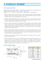
2.4 Construction and FeaturesDesign principle of our hydraulic snubber is a hydraulic system controlled by a valve mechanism. Themagnitude of generated resistance force is a function of input velocity.Namely, CVn = F ( C = constant, V = piston velocity, n = valve property, F = force generated)① Hydraulic cylinder is fully enclosed in the outer casing and they are filled with hydraulic fluid. A pistondivides the cylinder into two pressure chambers. They are hydraulically linked each other through afluid path formed by a pair of poppet valves and outer casing.② A poppet valve, being loaded by a built-in coil spring, stays open so far as the pressure in a fluidchamber is lower than the pre-determined threshold, and thus allowing reciprocal free movement ofthe piston during the thermal displacement mode of piping.③ The cubic volume of lateral piston rod, penetrating one of the chambers, causes a difference in fluidvolume in each chamber. An elastic accumulator, inserted between the cylinder wall and outercasing, functions as the self-adjustment means for offsetting the difference. For this designadvantage, Model SN/SNS snubber has no projection on the cylindrical body unlike conventionalsnubbers having outside oil reservoirs.④ Dynamic input displacement gives a quick driving force to the piston, and then causes a rapidpressure increase inside the compressed chamber. The valve on the compressed chamber side closesand the fluid path is shut off on the spot. Complete stop of fluid flow generates the resistant forceinside the cylinder to restrain the displacement.⑤ The entire process takes place against a reverse loading, and completely suppress the dynamicloading. (For Model SN only)⑥ Very precise through hole on the valve or peripherals keeps a minimum fluid flow even when it is inshut off position. For this design feature, the snubber unit is capable of allowing thermaldisplacement of the piping even during a dynamic oscillation of the piping system. This ability isdefined by so-called release rate or bleed rate. This function is not equipped for model SNS, as towithstand continuous one-way reaction force from safety valve, etc.2.5 Parts of Hydraulic Snubber2. HYDRAULIC SNUBBERNo. Part Name Material1 Holder SS400/S25C2 Casing SGP3 Cylinder Cover SS4004 Cylinder Tube STKM13C5 Rod Cover SS400/S25C6 Piston SS4007 Piston Rod S45C8 Tie-Rod S45C/SCM4359 Accumulator EPDM10 Casing Cover SS40011 Travel Indicator SUS304Size 03~ 25 12 Canvas Cover CLOTH8