Pipe Hangers, Supports & SnubbersConstant Spring Hangers
Constant Spring Hangers

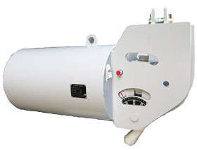
CSH-B1A
Constant Spring Hangers are designed to support piping and equipment where large vertical movements are expected and where the load variability of a variable spring hanger would exceed 25% of the design load. Constant Spring Hangers are also used where load variation over 6% is not permitted, even if the vertical movement is not large. STC Constant Spring Hangers are designed with a mechanism to provide a constant supporting load at any position throughout the travel range.
Standard Model & Type
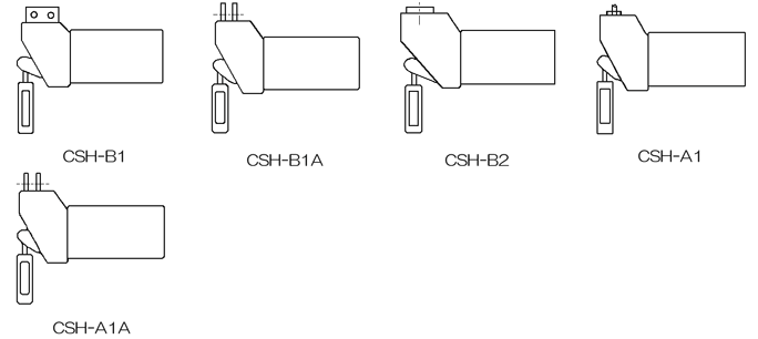
(1) Suspension Types (Horizontal)

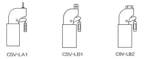
(2) Suspension Types (Vertical)

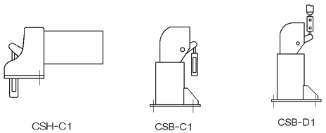
(3) Floor Mount Types

Applicable Load and Travel Range
| Load Range | 0.468kN~320.7kN |
|---|---|
| Maximum Travel Range | 50mm~400mm |
The most proper size shall be selected depending on the combination of maximum travel, design load and Model & Type.
For details, please see our Catalog No.2010HNGR or contact our sales or engineering department.
Standard Design Features of STC Constant Spring Hangers are as follows:
- In order to meet various application requirements, many Model & Type variations are provided :
- Suspension Model & Type: CSH – A1A, B1, B1A, B2 (Horizontal Spring Type)
- Suspension Model & Type: CSV – LB1, LB2, HA1 (Vertical Spring Type)
- Floor Mount Model & Type: CSB – C1, D1 (Vertical Spring Type) , CSH – C1 (Horizontal Spring Type)
- Coil Spring(s) is(are) pre-compressed and protected by the enclosed spring housing
- The spring coils are easily visible for inspection through a full length opening on the bottom of the housing.
- Dry bearings at all rotating points are used to minimize friction forces, and maintain load deviation within ±5% of the design load.
- Travel Stops for both upper and lower sides are provided in order to prevent full compression and excessive extension of coil spring(s).
- Each constant spring hanger is equipped with a Turnbuckle for field adjustment of hanger rod length.
- Load Adjustment of ±10% of the design load can be performed easily on site.
- Applicable Load Range is from 0.468kN to 320.7kN and travel range is from 50mm to 400mm with 10mm intervals.
The proper size is selected depending on the combination of maximum travel, design load and Model & Type.
Special designs for loads and travel beyond the standard size ranges are available upon request.

 All Products


